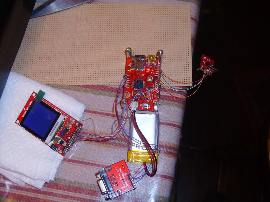
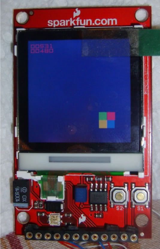
The ADC using the voltage on the VREF pin as a reference to compare ADC input against. VREF should be set to a value close to VCC (1)(pg 74). Vcc is 3.3V. The Accelerometer is tuned to operate at 3.0V (but can accept any voltage from 2.4 to 5 volts) (2)(pg 5). Ideally it would be good to set the VREF pin to 3.0V, but on the Logomatic V2 Board VREF is tied directly to VCC.(3)
The student connected the accelerometer to the LPC2148 in the following manner.
LPC-PIN ADXL-PIN
P1 X
P2 Y
VCC VCC
GND GND
The student then modified adc.h and adc.c from Phillips and produced MyAccelDriver.h and MyAccelDriver.c. main.c was also modified to test the functionality of the new accelerometer driver.
//****************************
// MyAccelDriver.h
//****************************
// Header file for ADC setup
// ELH April 3rd 2011
// The code herein was adapted from adc.h created Phillips Semiconducter Inc.
#ifndef _MY_ADC_
#define _MY_ADC_
#define ADC_CLOCK 3000000
#define ADC_MAX 3
#define ADC_MIN 2
#define ADC_OFFSET 0x10
#define ADC_INDEX 4
#define ADC_DONE 0x80000000
#define ADC_OVERRUN 0x40000000
#define ADC_ADINT 0x00010000
#include "type.h"
extern void ADCInit( DWORD clock);
extern WORD ADC0_Read( BYTE channelNum );
#endif
//****************************
// MyAccelDriver.c
//****************************
// The code Herein was adapted from adc.c created Phillips Semiconducter Inc.
include "LPC214x.h"
#include "type.h"
#include "target.h"
#include "MyAccelDriver.h"
void ADCInit( DWORD clock)
{
// initialize pins 2 and 3 of ADC0 for ADC input
// first clear bits 29:26 of PINSEL1 without modifying any other bits(pins)
// 11000011111111111111111111111111b
PINSEL1 &= 0xC3FFFFFF;
// now set bit 28 and 26 without modifying any other bits (pins)
// 00010100000000000000000000000000b
PINSEL1 |= 0x14000000;
AD0CR = ( 0x01 << 0 ) | // SEL=1,select channel 0, 1 to 4 on ADC0
( ( Fpclk / clock - 1 ) << 8 ) | // CLKDIV = Fpclk / 1000000 - 1
( 0 << 16 ) | // BURST = 0, no BURST, software controlled
( 0 << 17 ) | // CLKS = 0, 11 clocks/10 bits
( 1 << 21 ) | // PDN = 1, normal operation
( 0 << 22 ) | // TEST1:0 = 00
( 0 << 24 ) | // START = 0 A/D conversion stops
( 0 << 27 ); // EDGE = 0 (CAP/MAT singal falling,trigger A/D conversion)
}
WORD ADC0_Read( BYTE channel )
{
DWORD regVal;
WORD ADC_Data;
/* channel number is 2 through 3 */
if ( channel > ADC_MAX || channel < ADC_MIN)
{
channel = 2;
}
// clear channel bit
AD0CR &= 0xFFFFFF00;
// start conversion on a given channel
AD0CR |= (1 << 24) | (1 << channel);
while ( 1 ) // wait until end of A/D convert
{
regVal = *(volatile unsigned long *)(AD0_BASE_ADDR + ADC_OFFSET + ADC_INDEX * channel);
/* read result of A/D conversion */
if ( regVal & ADC_DONE )
{
break;
}
}
// stop ADC now
AD0CR &= 0xF8FFFFFF;
// save data when it's not overrun otherwise, return zero
if ( regVal & ADC_OVERRUN )
{
return ( 0 );
}
ADC_Data = ( regVal >> 6 ) & 0x3FF;
return ( ADC_Data ); // return A/D conversion value
}
//*******************************************************
// main.c
// Tests Screen and Accelerometer drivers
//*******************************************************
//Included Libraries for the LPC2148 ARM
#include "LPC214x.h" //Holds general addresses for the LPC2148 (Register Names, Interrupts addresses, Port Names/Numbers etc...)
#include "MyLCD_Driver.h"
#include "MyAccelDriver.h"
#include "system.h"
#include "target.h"
//General Definitions for Code Readability
//The pin numbers were found on the UberBoard v2 Schematic
#define RED_LED (1<<2) //The Red LED is on Port 0-Pin 18
#define GREEN_LED (1<<11) //The Green LED is on Port 0-Pin 19
int main (void)
{
int isRed = 1;
//*******************************************************
// Initialization
//*******************************************************
IODIR0 |= RED_LED | GREEN_LED;// | BLUE_LED; //Set the Red, Green and Blue LED pins as outputs
IOSET0 = RED_LED | GREEN_LED;// | BLUE_LED; //Initially turn all of the LED's off
LCDInit();
LCDClear(BLACK);
//Initialize ADC (just initializes channels 2 & 3 of ADC0
ADCInit(ADC_CLOCK);
//*******************************************************
// Main Code
//*******************************************************
LCDTestPixelSetOrder();
LCDPutStr("abcdefghijklm", 122, 122, RED, BLACK);
LCDPutStr("nopqrstuvwxyz", 122, 116, RED, BLACK);
LCDPutStr(" !&\"$%'()*+,-./", 122, 110, RED, BLACK);
LCDPutStr("0123456789:;?", 122, 104, RED, BLACK);
LCDPutStr("@[\\]^_`",122,98,RED,BLACK);
delay_ms(2000);
LCDSetArea(BLACK, 0, 98, 128, 30);
while(1)
{ //Now that everything is initialized, let's run an endless program loop
// which flashes LEDs and read the ADC
if (isRed == 1)
{
IOCLR0 = RED_LED; //Turn on the Red LED
IOSET0 = GREEN_LED;// | BLUE_LED; //Make sure Green and Blue are off
isRed = 0;
}
else
{
IOCLR0 = GREEN_LED; //Now turn the Green LED on
IOSET0 = RED_LED;// | BLUE_LED; //and turn off Red and Blue
isRed =1;
}
// Read the two ADC channels and output them to the screen.
WORD x = ADC0_Read(3);
WORD y = ADC0_Read(2);
// Report the values obtained from the accelerometer
// and the ADC
LCDPutWORD(x, 122, 122, RED, BLACK);
LCDPutWORD(y, 122, 116, RED, BLACK);
delay_ms(1000); //Delay for a second
}
return 0;
}
// End code files
(1) LPC214x Users Manual
(2) ADXL320 Datasheet
(3) Logomatic V2 Schematic


No comments:
Post a Comment