The first thing to consider when setting an General Purpose Input Output (GPIO) pin is whether it will be reading input or writing output. Like most other microcontrollers, this is done on the LPC2148 by assigning an IO direction to each pin of interest. When setting up the display driver the student set four pins (22,21,19,17) as outputs. Setting up the two GPIO pins for analog input/output is likely be more involved.
To set the pins as input pins they need to be added to the IODIR1 register. Below is an example of C code setting the GPIO pins P1 and P2 to inputs and pins P5 and P6 as outputs. The pins SCLK and MOSI from the serial controller are also set as outputs.
//Begin Example
// The GPIO pins P1 and P2 are pins 30 and 29 respectively)
// P5 and P6 are
#define P1 (1<<30)
#define P2 (1<<29)
#define LCD_RES (1<<22) // P5
#define LCD_CS (1<<21) // P6
#define LCD_DIO (1<<19)
#define LCD_SCK (1<<17)
int main(void)
{
IODIR1 |= (P1 | P2);
IODIR0 |= (LCD_DIO | LCD_SCK | LCD_CS | LCD_RES);
// .....
}
// End Example
Setting the GPIO pins as inputs or outputs is a trivial setup operation.
In examining the LPC2148 documentation the student found the PINSEL0, PINSEL1 and PINSEL2 registers. These registers control the pin connect block, which allows the micro-controller to configure pins for different functions. The pin control block is described in detail in the 214x Users Manual, pages 75-80.
The student will use the pin select registers to enable the ADC in pin under Accelerometer Registers, Setup and Use
(1) LPC214x Users Manual
Thursday, March 31, 2011
Tuesday, March 29, 2011
Display Driver Part 4
After displaying all characters of my font, using the code below, the noticed mistakes on the characters 1^-@;
// main.cpp
int main (void)
{
//*******************************************************
// Initialization
//*******************************************************
IODIR0 |= RED_LED | GREEN_LED; //Set the Red and Green LED pins as outputs
IOSET0 = RED_LED | GREEN_LED;//Initially turn all of the LED's off
//*******************************************************
// Main Code
//*******************************************************
LCDInit();
LCDClear(BLACK);
LCDTestPixelSetOrder();
LCDPutStr("abcdefghijklm", 122, 122, RED, BLACK);
LCDPutStr("nopqrstuvwxyz", 122, 116, RED, BLACK);
LCDPutStr(" !&\"$%'()*+,-./", 122, 110, RED, BLACK);
LCDPutStr("0123456789:;?", 122, 104, RED, BLACK);
LCDPutStr("@[\\]^_`",122,98,RED,BLACK);
return 0;
}
// the following two functions exist in LCD_Driver.cpp, there also exists LCD_Driver.h
extern const unsigned char FONT5x5[91][5];
void LCDPutChar(char c, int x, int y, int fColor, int bColor)
{
int i,j;
unsigned int nCols;
unsigned int nRows;
unsigned int nBytes;
unsigned char PixelRow;
unsigned char Mask;
unsigned int Word0;
unsigned int Word1;
// get the nColumns, nRows and nBytes
// hard coded for now, not ideal
nCols = 6;
nRows = 5;
nBytes = 5;
// get pointer to the first byte of the desired character
PixelRow = FONT5x5[c-32][0];
// Row address set (command 0x2B)
LCDCommand(PASET);
LCDData(y);
LCDData(y + nRows - 1);
// Column address set (command 0x2A)
LCDCommand(CASET);
LCDData(x);
LCDData(x + nCols- 1);
// WRITE MEMORY
LCDCommand(RAMWR);
// loop on each row, working backwards from the bottom to the top
for (i = 0; i < nRows; i++)
{
// copy pixel row from font table and then decrement row
PixelRow = FONT5x5[c-32][i];
// loop on each pixel in the row (left to right)
// Note: we do two pixels each loop
Mask = 0x1;
//if (nCols%2 == 1)
//{
// nCols++;
//}
for (j = 0; j < nCols; j += 2) {
// if pixel bit set, use foreground color; else use the background color
// now get the pixel color for two successive pixels
if ((PixelRow & Mask) == 0)
Word0 = bColor;
else
Word0 = fColor;
Mask = Mask << 1;
if ((PixelRow & Mask) == 0)
Word1 = bColor;
else
Word1 = fColor;
Mask = Mask << 1;
// use this information to output three data bytes
LCDData((Word0 >> 4) & 0xFF);
LCDData(((Word0 & 0xF) << 4) | ((Word1 >> 8) & 0xF));
LCDData(Word1 & 0xFF);
}
}
// terminate the Write Memory command
LCDCommand(NOP);
}
void LCDPutStr(char *pString, int x, int y, int fColor, int bColor)
{
// loop until null-terminator is seen
while (*pString != 0x00)
{
// draw the character
LCDPutChar(*pString++, x, y, fColor, bColor);
// advance the x position
x = x - 6;
if (x > 131 || x < 0) break;
}
}
// this is in the file font.c (there exists a font.h too)
extern const unsigned char FONT5x5[91][5] =
{ 0x00, 0x00, 0x00, 0x00, 0x00, 0x10, 0x00, 0x10, 0x10, 0x10, // ' ' !
0x00, 0x00, 0x00, 0x0a, 0x0a, 0x0a, 0x1f, 0x0a, 0x1f, 0x0a, // " #
0x02, 0x07, 0x07, 0x07, 0x02, 0x10, 0x0a, 0x04, 0x0a, 0x01, // $ %
0x1e, 0x13, 0x1e, 0x12, 0x1e, 0x00, 0x00, 0x00, 0x08, 0x08, // & '
0x02, 0x04, 0x04, 0x04, 0x02, 0x08, 0x04, 0x04, 0x04, 0x08, // ( )
0x00, 0x0a, 0x04, 0x0e, 0x04, 0x00, 0x04, 0x0e, 0x04, 0x00, // * +
0x10, 0x08, 0x00, 0x00, 0x00, 0x00, 0x00, 0x0e, 0x00, 0x00, // , -
0x10, 0x00, 0x00, 0x00, 0x00, 0x10, 0x08, 0x04, 0x02, 0x01, // . /
0x1f, 0x11, 0x11, 0x11, 0x1f, 0x0e, 0x04, 0x04, 0x04, 0x0c, // 0 1
0x1f, 0x10, 0x1f, 0x01, 0x1e, 0x1f, 0x01, 0x0f, 0x01, 0x1f, // 2 3
0x02, 0x1f, 0x0a, 0x06, 0x02, 0x1e, 0x01, 0x1f, 0x10, 0x1f, // 4 5
0x1f, 0x11, 0x1f, 0x10, 0x0f, 0x08, 0x04, 0x02, 0x01, 0x1f, // 6 7
0x1f, 0x11, 0x1f, 0x11, 0x1f, 0x1f, 0x01, 0x1f, 0x11, 0x1f, // 8 9
0x00, 0x08, 0x00, 0x08, 0x00, 0x10, 0x08, 0x00, 0x08, 0x00, // : ;
0x00, 0x04, 0x08, 0x04, 0x00, 0x00, 0x0e, 0x00, 0x0e, 0x00, // < =
0x00, 0x04, 0x02, 0x04, 0x00, 0x04, 0x00, 0x06, 0x02, 0x0e, // > ?
0x1e, 0x1a, 0x1e, 0x1e, 0x00, 0x11, 0x11, 0x1f, 0x11, 0x1f, // @ A
0x1f, 0x11, 0x1e, 0x11, 0x1f, 0x1f, 0x11, 0x10, 0x11, 0x1f, // B C
0x1e, 0x11, 0x11, 0x11, 0x1e, 0x1f, 0x10, 0x1e, 0x10, 0x1f, // D E
0x10, 0x10, 0x1e, 0x10, 0x1f, 0x1f, 0x11, 0x13, 0x10, 0x1f, // F G
0x11, 0x11, 0x1f, 0x11, 0x11, 0x0e, 0x04, 0x04, 0x04, 0x0e, // H I
0x1f, 0x11, 0x01, 0x01, 0x01, 0x11, 0x12, 0x1c, 0x12, 0x11, // J K
0x1f, 0x10, 0x10, 0x10, 0x10, 0x15, 0x15, 0x15, 0x15, 0x1b, // L M
0x11, 0x13, 0x15, 0x19, 0x11, 0x1f, 0x11, 0x11, 0x11, 0x1f, // N O
0x10, 0x10, 0x1f, 0x11, 0x1f, 0x1f, 0x13, 0x11, 0x11, 0x1f, // P Q
0x11, 0x12, 0x1f, 0x11, 0x1f, 0x1f, 0x01, 0x1f, 0x10, 0x1f, // R S
0x04, 0x04, 0x04, 0x04, 0x1f, 0x1f, 0x11, 0x11, 0x11, 0x11, // T U
0x04, 0x0a, 0x11, 0x11, 0x11, 0x1b, 0x15, 0x15, 0x15, 0x15, // V W
0x11, 0x0a, 0x04, 0x0a, 0x11, 0x1f, 0x01, 0x1f, 0x11, 0x11, // X Y
0x1f, 0x08, 0x04, 0x02, 0x1f, 0x06, 0x04, 0x04, 0x04, 0x06, // Z [
0x01, 0x02, 0x04, 0x08, 0x10, 0x0c, 0x04, 0x04, 0x04, 0x0c, // \ ]
0x00, 0x00, 0x00, 0x0a, 0x04, 0x1f, 0x00, 0x00, 0x00, 0x00, // ^ _
0x00, 0x00, 0x00, 0x08, 0x10, 0x11, 0x11, 0x1f, 0x11, 0x1f, // ` A
0x1f, 0x11, 0x1e, 0x11, 0x1f, 0x1f, 0x11, 0x10, 0x11, 0x1f, // B C
0x1e, 0x11, 0x11, 0x11, 0x1e, 0x1f, 0x10, 0x1e, 0x10, 0x1f, // D E
0x10, 0x10, 0x1e, 0x10, 0x1f, 0x1f, 0x11, 0x13, 0x10, 0x1f, // F G
0x11, 0x11, 0x1f, 0x11, 0x11, 0x0e, 0x04, 0x04, 0x04, 0x0e, // H I
0x1f, 0x11, 0x01, 0x01, 0x01, 0x11, 0x12, 0x1c, 0x12, 0x11, // J K
0x1f, 0x10, 0x10, 0x10, 0x10, 0x15, 0x15, 0x15, 0x15, 0x1b, // L M
0x11, 0x13, 0x15, 0x19, 0x11, 0x1f, 0x11, 0x11, 0x11, 0x1f, // N O
0x10, 0x10, 0x1f, 0x11, 0x1f, 0x1f, 0x13, 0x11, 0x11, 0x1f, // P Q
0x11, 0x12, 0x1f, 0x11, 0x1f, 0x1f, 0x01, 0x1f, 0x10, 0x1f, // R S
0x04, 0x04, 0x04, 0x04, 0x1f, 0x1f, 0x11, 0x11, 0x11, 0x11, // T U
0x04, 0x0a, 0x11, 0x11, 0x11, 0x1b, 0x15, 0x15, 0x15, 0x15, // V W
0x11, 0x0a, 0x04, 0x0a, 0x11, 0x1f, 0x01, 0x1f, 0x11, 0x11, // X Y
0x1f, 0x08, 0x04, 0x02, 0x1f}; // Z
Below is the output to the driver additions outlined in the last few posts. Along with the font "bored" that I used as a guide.
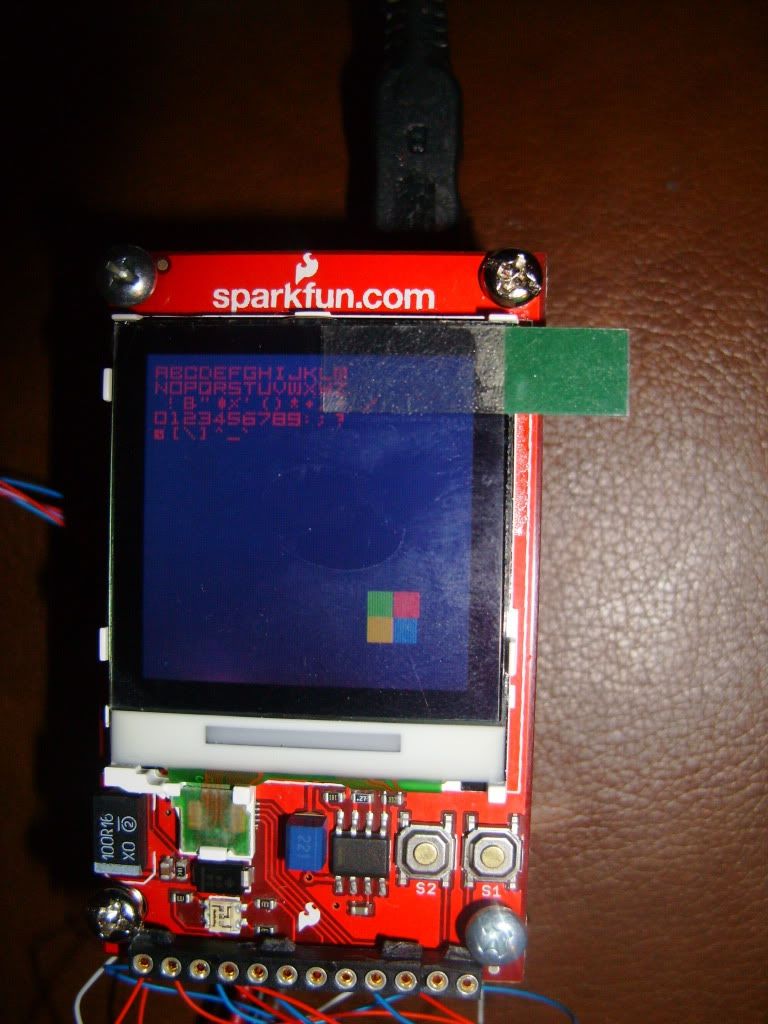
As can be seen the font is just enough to be functional, and that the colors at the bottom right seem to take different amounts of space. After testing a bit it can be shown that different colors seem to be aligned differently on the screen even thou they should occupy the same columns on the screen. Care will be needed to avoid graphics looking funny on the screen.
// main.cpp
int main (void)
{
//*******************************************************
// Initialization
//*******************************************************
IODIR0 |= RED_LED | GREEN_LED; //Set the Red and Green LED pins as outputs
IOSET0 = RED_LED | GREEN_LED;//Initially turn all of the LED's off
//*******************************************************
// Main Code
//*******************************************************
LCDInit();
LCDClear(BLACK);
LCDTestPixelSetOrder();
LCDPutStr("abcdefghijklm", 122, 122, RED, BLACK);
LCDPutStr("nopqrstuvwxyz", 122, 116, RED, BLACK);
LCDPutStr(" !&\"$%'()*+,-./", 122, 110, RED, BLACK);
LCDPutStr("0123456789:;?", 122, 104, RED, BLACK);
LCDPutStr("@[\\]^_`",122,98,RED,BLACK);
return 0;
}
// the following two functions exist in LCD_Driver.cpp, there also exists LCD_Driver.h
extern const unsigned char FONT5x5[91][5];
void LCDPutChar(char c, int x, int y, int fColor, int bColor)
{
int i,j;
unsigned int nCols;
unsigned int nRows;
unsigned int nBytes;
unsigned char PixelRow;
unsigned char Mask;
unsigned int Word0;
unsigned int Word1;
// get the nColumns, nRows and nBytes
// hard coded for now, not ideal
nCols = 6;
nRows = 5;
nBytes = 5;
// get pointer to the first byte of the desired character
PixelRow = FONT5x5[c-32][0];
// Row address set (command 0x2B)
LCDCommand(PASET);
LCDData(y);
LCDData(y + nRows - 1);
// Column address set (command 0x2A)
LCDCommand(CASET);
LCDData(x);
LCDData(x + nCols- 1);
// WRITE MEMORY
LCDCommand(RAMWR);
// loop on each row, working backwards from the bottom to the top
for (i = 0; i < nRows; i++)
{
// copy pixel row from font table and then decrement row
PixelRow = FONT5x5[c-32][i];
// loop on each pixel in the row (left to right)
// Note: we do two pixels each loop
Mask = 0x1;
//if (nCols%2 == 1)
//{
// nCols++;
//}
for (j = 0; j < nCols; j += 2) {
// if pixel bit set, use foreground color; else use the background color
// now get the pixel color for two successive pixels
if ((PixelRow & Mask) == 0)
Word0 = bColor;
else
Word0 = fColor;
Mask = Mask << 1;
if ((PixelRow & Mask) == 0)
Word1 = bColor;
else
Word1 = fColor;
Mask = Mask << 1;
// use this information to output three data bytes
LCDData((Word0 >> 4) & 0xFF);
LCDData(((Word0 & 0xF) << 4) | ((Word1 >> 8) & 0xF));
LCDData(Word1 & 0xFF);
}
}
// terminate the Write Memory command
LCDCommand(NOP);
}
void LCDPutStr(char *pString, int x, int y, int fColor, int bColor)
{
// loop until null-terminator is seen
while (*pString != 0x00)
{
// draw the character
LCDPutChar(*pString++, x, y, fColor, bColor);
// advance the x position
x = x - 6;
if (x > 131 || x < 0) break;
}
}
// this is in the file font.c (there exists a font.h too)
extern const unsigned char FONT5x5[91][5] =
{ 0x00, 0x00, 0x00, 0x00, 0x00, 0x10, 0x00, 0x10, 0x10, 0x10, // ' ' !
0x00, 0x00, 0x00, 0x0a, 0x0a, 0x0a, 0x1f, 0x0a, 0x1f, 0x0a, // " #
0x02, 0x07, 0x07, 0x07, 0x02, 0x10, 0x0a, 0x04, 0x0a, 0x01, // $ %
0x1e, 0x13, 0x1e, 0x12, 0x1e, 0x00, 0x00, 0x00, 0x08, 0x08, // & '
0x02, 0x04, 0x04, 0x04, 0x02, 0x08, 0x04, 0x04, 0x04, 0x08, // ( )
0x00, 0x0a, 0x04, 0x0e, 0x04, 0x00, 0x04, 0x0e, 0x04, 0x00, // * +
0x10, 0x08, 0x00, 0x00, 0x00, 0x00, 0x00, 0x0e, 0x00, 0x00, // , -
0x10, 0x00, 0x00, 0x00, 0x00, 0x10, 0x08, 0x04, 0x02, 0x01, // . /
0x1f, 0x11, 0x11, 0x11, 0x1f, 0x0e, 0x04, 0x04, 0x04, 0x0c, // 0 1
0x1f, 0x10, 0x1f, 0x01, 0x1e, 0x1f, 0x01, 0x0f, 0x01, 0x1f, // 2 3
0x02, 0x1f, 0x0a, 0x06, 0x02, 0x1e, 0x01, 0x1f, 0x10, 0x1f, // 4 5
0x1f, 0x11, 0x1f, 0x10, 0x0f, 0x08, 0x04, 0x02, 0x01, 0x1f, // 6 7
0x1f, 0x11, 0x1f, 0x11, 0x1f, 0x1f, 0x01, 0x1f, 0x11, 0x1f, // 8 9
0x00, 0x08, 0x00, 0x08, 0x00, 0x10, 0x08, 0x00, 0x08, 0x00, // : ;
0x00, 0x04, 0x08, 0x04, 0x00, 0x00, 0x0e, 0x00, 0x0e, 0x00, // < =
0x00, 0x04, 0x02, 0x04, 0x00, 0x04, 0x00, 0x06, 0x02, 0x0e, // > ?
0x1e, 0x1a, 0x1e, 0x1e, 0x00, 0x11, 0x11, 0x1f, 0x11, 0x1f, // @ A
0x1f, 0x11, 0x1e, 0x11, 0x1f, 0x1f, 0x11, 0x10, 0x11, 0x1f, // B C
0x1e, 0x11, 0x11, 0x11, 0x1e, 0x1f, 0x10, 0x1e, 0x10, 0x1f, // D E
0x10, 0x10, 0x1e, 0x10, 0x1f, 0x1f, 0x11, 0x13, 0x10, 0x1f, // F G
0x11, 0x11, 0x1f, 0x11, 0x11, 0x0e, 0x04, 0x04, 0x04, 0x0e, // H I
0x1f, 0x11, 0x01, 0x01, 0x01, 0x11, 0x12, 0x1c, 0x12, 0x11, // J K
0x1f, 0x10, 0x10, 0x10, 0x10, 0x15, 0x15, 0x15, 0x15, 0x1b, // L M
0x11, 0x13, 0x15, 0x19, 0x11, 0x1f, 0x11, 0x11, 0x11, 0x1f, // N O
0x10, 0x10, 0x1f, 0x11, 0x1f, 0x1f, 0x13, 0x11, 0x11, 0x1f, // P Q
0x11, 0x12, 0x1f, 0x11, 0x1f, 0x1f, 0x01, 0x1f, 0x10, 0x1f, // R S
0x04, 0x04, 0x04, 0x04, 0x1f, 0x1f, 0x11, 0x11, 0x11, 0x11, // T U
0x04, 0x0a, 0x11, 0x11, 0x11, 0x1b, 0x15, 0x15, 0x15, 0x15, // V W
0x11, 0x0a, 0x04, 0x0a, 0x11, 0x1f, 0x01, 0x1f, 0x11, 0x11, // X Y
0x1f, 0x08, 0x04, 0x02, 0x1f, 0x06, 0x04, 0x04, 0x04, 0x06, // Z [
0x01, 0x02, 0x04, 0x08, 0x10, 0x0c, 0x04, 0x04, 0x04, 0x0c, // \ ]
0x00, 0x00, 0x00, 0x0a, 0x04, 0x1f, 0x00, 0x00, 0x00, 0x00, // ^ _
0x00, 0x00, 0x00, 0x08, 0x10, 0x11, 0x11, 0x1f, 0x11, 0x1f, // ` A
0x1f, 0x11, 0x1e, 0x11, 0x1f, 0x1f, 0x11, 0x10, 0x11, 0x1f, // B C
0x1e, 0x11, 0x11, 0x11, 0x1e, 0x1f, 0x10, 0x1e, 0x10, 0x1f, // D E
0x10, 0x10, 0x1e, 0x10, 0x1f, 0x1f, 0x11, 0x13, 0x10, 0x1f, // F G
0x11, 0x11, 0x1f, 0x11, 0x11, 0x0e, 0x04, 0x04, 0x04, 0x0e, // H I
0x1f, 0x11, 0x01, 0x01, 0x01, 0x11, 0x12, 0x1c, 0x12, 0x11, // J K
0x1f, 0x10, 0x10, 0x10, 0x10, 0x15, 0x15, 0x15, 0x15, 0x1b, // L M
0x11, 0x13, 0x15, 0x19, 0x11, 0x1f, 0x11, 0x11, 0x11, 0x1f, // N O
0x10, 0x10, 0x1f, 0x11, 0x1f, 0x1f, 0x13, 0x11, 0x11, 0x1f, // P Q
0x11, 0x12, 0x1f, 0x11, 0x1f, 0x1f, 0x01, 0x1f, 0x10, 0x1f, // R S
0x04, 0x04, 0x04, 0x04, 0x1f, 0x1f, 0x11, 0x11, 0x11, 0x11, // T U
0x04, 0x0a, 0x11, 0x11, 0x11, 0x1b, 0x15, 0x15, 0x15, 0x15, // V W
0x11, 0x0a, 0x04, 0x0a, 0x11, 0x1f, 0x01, 0x1f, 0x11, 0x11, // X Y
0x1f, 0x08, 0x04, 0x02, 0x1f}; // Z
Below is the output to the driver additions outlined in the last few posts. Along with the font "bored" that I used as a guide.


As can be seen the font is just enough to be functional, and that the colors at the bottom right seem to take different amounts of space. After testing a bit it can be shown that different colors seem to be aligned differently on the screen even thou they should occupy the same columns on the screen. Care will be needed to avoid graphics looking funny on the screen.
Saturday, March 26, 2011
Display Driver Part 3
It is counter intuitive to the author to print a string from right to left. With the origin of the co-ordinates in the lower right hand part of the screen, the pixels of each character would need to be output from right to left. It seems like flipping the X axis will be worthwhile task. Unfortunately there is no command to support this.(1)
Because areas are filled by row and not by columns, the font to hex map contained in part 1 is not ideal. The map will need to be redone in relation to rows instead of columns. Taking the example from part 1, the letter A.
11111 -> 0x1F
10001 -> 0x11
11111 -> 0x1F
10001 -> 0x11
10001 -> 0x11
Since the pixels draw from the bottom up this would be stored in memory as {0x11, 0x11, 0x1F, 0x11, 0x1F}. MSB is on the left LSB on the right.
New hex map
// starts with the ASCI value 32
// all characters used the bored font except for " # % ( ) * + , - / 1 7 : ; = I [ \ ] ^ _ `
{ 0x00, 0x00, 0x00, 0x00, 0x00, 0x10, 0x00, 0x10, 0x10, 0x10, // ' ' !
0x00, 0x00, 0x00, 0x0a, 0x0a, 0x0a, 0x1f, 0x0a, 0x1f, 0x0a, // " #
0x02, 0x07, 0x07, 0x07, 0x02, 0x10, 0x0a, 0x04, 0x0a, 0x01, // $ %
0x1e, 0x13, 0x1e, 0x12, 0x1e, 0x00, 0x00, 0x00, 0x08, 0x08, // & '
0x02, 0x04, 0x04, 0x04, 0x02, 0x08, 0x04, 0x04, 0x04, 0x08, // ( )
0x00, 0x0a, 0x04, 0x0a, 0x04, 0x00, 0x04, 0x0e, 0x04, 0x00, // * +
0x10, 0x08, 0x00, 0x00, 0x00, 0x00, 0x00, 0x0a, 0x00, 0x00, // , -
0x10, 0x00, 0x00, 0x00, 0x00, 0x10, 0x08, 0x04, 0x02, 0x01, // . /
0x1f, 0x11, 0x11, 0x11, 0x1f, 0x0a, 0x04, 0x04, 0x04, 0x0c, // 0 1
0x1f, 0x10, 0x1f, 0x01, 0x1e, 0x1f, 0x01, 0x0f, 0x01, 0x1f, // 2 3
0x02, 0x1f, 0x0a, 0x06, 0x02, 0x1e, 0x01, 0x1f, 0x10, 0x1f, // 4 5
0x1f, 0x11, 0x1f, 0x10, 0x0f, 0x08, 0x04, 0x02, 0x01, 0x1f, // 6 7
0x1f, 0x11, 0x1f, 0x11, 0x1f, 0x1f, 0x01, 0x1f, 0x11, 0x1f, // 8 9
0x00, 0x08, 0x00, 0x08, 0x00, 0x08, 0x08, 0x00, 0x08, 0x00, // : ;
0x00, 0x04, 0x08, 0x04, 0x00, 0x00, 0x0e, 0x00, 0x0e, 0x00, // < =
0x00, 0x04, 0x02, 0x04, 0x00, 0x04, 0x00, 0x06, 0x02, 0x0e, // > ?
0x1e, 0x1c, 0x1e, 0x1e, 0x00, 0x11, 0x11, 0x1f, 0x11, 0x1f, // @ A
0x1f, 0x11, 0x1e, 0x11, 0x1f, 0x1f, 0x11, 0x10, 0x11, 0x1f, // B C
0x1e, 0x11, 0x11, 0x11, 0x1e, 0x1f, 0x10, 0x1e, 0x10, 0x1f, // D E
0x10, 0x10, 0x1e, 0x10, 0x1f, 0x1f, 0x11, 0x13, 0x10, 0x1f, // F G
0x11, 0x11, 0x1f, 0x11, 0x11, 0x0e, 0x04, 0x04, 0x04, 0x0e, // H I
0x1f, 0x11, 0x01, 0x01, 0x01, 0x11, 0x12, 0x1c, 0x12, 0x11, // J K
0x1f, 0x10, 0x10, 0x10, 0x10, 0x15, 0x15, 0x15, 0x15, 0x1b, // L M
0x11, 0x13, 0x15, 0x19, 0x11, 0x1f, 0x11, 0x11, 0x11, 0x1f, // N O
0x10, 0x10, 0x1f, 0x11, 0x1f, 0x1f, 0x13, 0x11, 0x11, 0x1f, // P Q
0x11, 0x12, 0x1f, 0x11, 0x1f, 0x1f, 0x01, 0x1f, 0x10, 0x1f, // R S
0x04, 0x04, 0x04, 0x04, 0x1f, 0x1f, 0x11, 0x11, 0x11, 0x11, // T U
0x04, 0x0a, 0x11, 0x11, 0x11, 0x1b, 0x15, 0x15, 0x15, 0x15, // V W
0x11, 0x0a, 0x04, 0x0a, 0x11, 0x1f, 0x01, 0x1f, 0x11, 0x11, // X Y
0x1f, 0x08, 0x04, 0x02, 0x1f, 0x06, 0x04, 0x04, 0x04, 0x06, // Z [
0x01, 0x02, 0x04, 0x08, 0x10, 0x0c, 0x04, 0x04, 0x04, 0x0c, // \ ]
0x00, 0x00, 0x00, 0x0c, 0x04, 0x1f, 0x00, 0x00, 0x00, 0x00, // ^ _
0x00, 0x00, 0x00, 0x08, 0x10, 0x11, 0x11, 0x1f, 0x11, 0x1f, // ` A
0x1f, 0x11, 0x1e, 0x11, 0x1f, 0x1f, 0x11, 0x10, 0x11, 0x1f, // B C
0x1e, 0x11, 0x11, 0x11, 0x1e, 0x1f, 0x10, 0x1e, 0x10, 0x1f, // D E
0x10, 0x10, 0x1e, 0x10, 0x1f, 0x1f, 0x11, 0x13, 0x10, 0x1f, // F G
0x11, 0x11, 0x1f, 0x11, 0x11, 0x0e, 0x04, 0x04, 0x04, 0x0e, // H I
0x1f, 0x11, 0x01, 0x01, 0x01, 0x11, 0x12, 0x1c, 0x12, 0x11, // J K
0x1f, 0x10, 0x10, 0x10, 0x10, 0x15, 0x15, 0x15, 0x15, 0x1b, // L M
0x11, 0x13, 0x15, 0x19, 0x11, 0x1f, 0x11, 0x11, 0x11, 0x1f, // N O
0x10, 0x10, 0x1f, 0x11, 0x1f, 0x1f, 0x13, 0x11, 0x11, 0x1f, // P Q
0x11, 0x12, 0x1f, 0x11, 0x1f, 0x1f, 0x01, 0x1f, 0x10, 0x1f, // R S
0x04, 0x04, 0x04, 0x04, 0x1f, 0x1f, 0x11, 0x11, 0x11, 0x11, // T U
0x04, 0x0a, 0x11, 0x11, 0x11, 0x1b, 0x15, 0x15, 0x15, 0x15, // V W
0x11, 0x0a, 0x04, 0x0a, 0x11, 0x1f, 0x01, 0x1f, 0x11, 0x11, // X Y
0x1f, 0x08, 0x04, 0x02, 0x1f} // Z
Epson Controller (1) pg. 30
Changes to LCD Driver Initialization
While trying to discover which direction the pixels fill in while writing to an area, the student noticed some odd behavior.
The order in which the rows were written out was off. The LPC driver I was building off from had a setting that when initialized was causing the problem.
Old Code:
LCDCommand(DATCTL); // data control(EPSON)
LCDData(0x03); //correct for normal sin7
LCDData(0x00); // normal RGB arrangement
LCDData(0x02); // 16-bit Grayscale Type A
New Code:
LCDCommand(DATCTL); // data control(EPSON)
LCDData(0x00); // This is the column write direction
LCDData(0x00); // normal RGB arrangement
LCDData(0x02); // 16-bit Grayscale Type A
Changing the column write direction fixed the problems with filling an area for this system.
The Student found that the contrast could be tweaked to display colors more clearly as seen belo
Old Code:
LCDCommand(VOLCTR); // electronic volume, this is the contrast/brightness(EPSON)
LCDData(0x24); // volume (contrast) setting - fine tuning, original
LCDData(0x03); // internal resistor ratio - coarse adjustment
New Code:
LCDCommand(VOLCTR); // electronic volume, this is the contrast/brightness(EPSON)
LCDData(0x22); // volume (contrast) setting - fine tuning, original
// This setting acts like a cross between contrast and brightness on a television
LCDData(0x03); // internal resistor ratio - coarse adjustment
Just a small adjustment was needed to improve the picture.
Display Driver Part 2
Screen Orientation. Out of the box the screen looks to be oriented with the position 0,0 in the lower right hand corner. It would be more convenient to re-orient the co-ordinates so that the 0,0 is in the lower left hand part of the screen (or even upper right). It may or may not be worth the time that it takes to discover the command and syntax to re-orient the screen. With a bit of fiddling the student was able to confirm that Columns correspond to to vertical columns and Pages correspond to Horizontal rows on the screen.
On the Epson Controller the command PASET sets the page boundary, the command CASET sets the column boundaries. To define a box, first send the command PASET followed by the two individual rows that form the horizontal borders. Then send the command CASET followed by two individual columns that form the vertical borders. The intersection of these for lines forms the area which you can send color information to. The command RAMWR allows the controller to enter mode where The color data needs to be sent for each pixel in the area. (If in 2048 color mode you send 3 bytes at a time that set two pixels at a time, the code example is for 2048 colors) The following code demonstrates how to set a rectangle to a solid color.
void LCDSetArea(int color,
unsigned char botRigX, unsigned char botRigY,
unsigned char width, unsigned char height)
{
LCDCommand(PASET); // page start/end ram
LCDData(botRigY);
LCDData(botRigY + height);
LCDCommand(CASET); // column start/end ram
LCDData(botRigX);
LCDData(botRigX + width);
LCDCommand(RAMWR); // write
for(int count= 0; count < (width+1) * (height+1)/2; count ++)
{
LCDData((color>>4)&0x00FF);
LCDData(((color&0x0F)<<4)|(color>>8));
LCDData(color&0x0FF);
}
}
The pixels in the area are set one by one sequentially, as seen in the loop of the function above. The student knows that they are set either by column or by row. To determine the exact order of this the student wrote and invoked the following function. While running the function a few problems were discovered as outlined in Changes to Driver Initialization.
void LCDTestPixelSetOrder()
{
#ifdef EPSON
unsigned char botRigY = 20;
unsigned char botRigX = 20;
unsigned char width = 19;
unsigned char height = 19;
int color = GREEN;
LCDCommand(PASET); // page start/end ram
LCDData(botRigY);
LCDData(botRigY + height);
LCDCommand(CASET); // column start/end ram
LCDData(botRigX);
LCDData(botRigX + width);
LCDCommand(RAMWR); // write
for(int count= 0; count < (width+1) * (height+1) /2; count ++)
{
// different color set when halfway done
if (count >= ((width+1) * (height+1)) / 4)
{
// red and green
if ( (count/5)%2 == 0)
color = RED;
else
color = GREEN;
}
else
{
// blue and Yellow
if ( (count/5)%2 == 0)
color = BLUE;
else
color = YELLOW;
}
LCDData((color>>4)&0x00FF);
LCDData(((color&0x0F)<<4)|(color>>8));
LCDData(color&0x0FF); // nop(EPSON)
}
#endif
}
As one would expect the areas fill by rows in ascending order, as follows below.
10, 2<----<----0,2<---+
|
+---------->-------+
|
10,1<----<-----0,1<---+
|
+-->----->-------+
|
10,0<----<-----0,0
3-26-2011 Notes of work done over the past week.
A component on the LCD breakout board is getting quite hot. At first I thought I was putting too much voltage into the vBatt Pin and I was thinking about putting less voltage in. As it turns out if I would have done this I would have made the problem worse. Upon inspecting the board I realized the component that was getting hot to the touch was the voltage multiplier, had I cut the voltage I would probably have made the problem worse, or maybe even damaged the component.
As taken from the Sparkfun web page for the device (1):
In my original specification I called for a USB game pad to be attached to the LPC2418 as an input. I had scoured the LPC2418 documentation and could not find any interface that would allow the Microcontroller to act as a USB host. Finally I found that the LPC241X series supports USB client mode but does not support host mode (2)(3). The project will have to be revised since the USB game pad will not be able to be attached.
Because the USB game pad will not work with the system some other form of user input will need to be arranged. The design includes the accelerometer will be acceptable for directional game control, but does not seem ideal for allowing the user to 'select' or 'confirm' a choice. Some kind of button seems like it would be the most natural way for the user to be able to interact with the device in certain ways.
The LCD breakout board has two buttons available on the device(1), but they are set below the level of the screen, making them difficult to push, also, one of the buttons is close to the voltage multiplier - which is hot to the touch. As they are, the buttons on the LCD board are not an ideal solution, they would need to be modified if they would be used at all. Another option is to buy an additional button or two and wire them to one or two of the ADC pins. It may be harder to find buttons that fit over the buttons on the LCD board, but they would not get in the way of a case. Other switches will be common and cheap, but could get in the way of creating a case for the system. (perhaps the buttons could be mounted horizontally under the LCD board so they don't stick out a lot)
If there is an extra ADC pin, it would be nice to pipe power to the accelerometer from an ADC pin instead of power. That way it would be possible to only give power to the accelerometer when the system is ready for accelerometer input.
Before connecting the accelerometer, it would be nice to have strings printing to the screen for visual feedback.
LCD Breakout Page (1)
USB for LPCXXXX (2)
LPC241X Datasheet (3) Page 16
As taken from the Sparkfun web page for the device (1):
+Vbat and the 3.3V input can be driven from the same regulated 3.3V source, but the device will draw more current than if the +Vbat input was driven from a higher source voltage. For a given +Vbat input voltage, you can expect the current draw to be:
- 108mA @ 6V input
- 120mA @ 5V input
- 243mA @ 3.7V input (single Lipo cell)
- 324mA @ 3.3V input
In my original specification I called for a USB game pad to be attached to the LPC2418 as an input. I had scoured the LPC2418 documentation and could not find any interface that would allow the Microcontroller to act as a USB host. Finally I found that the LPC241X series supports USB client mode but does not support host mode (2)(3). The project will have to be revised since the USB game pad will not be able to be attached.
Because the USB game pad will not work with the system some other form of user input will need to be arranged. The design includes the accelerometer will be acceptable for directional game control, but does not seem ideal for allowing the user to 'select' or 'confirm' a choice. Some kind of button seems like it would be the most natural way for the user to be able to interact with the device in certain ways.
The LCD breakout board has two buttons available on the device(1), but they are set below the level of the screen, making them difficult to push, also, one of the buttons is close to the voltage multiplier - which is hot to the touch. As they are, the buttons on the LCD board are not an ideal solution, they would need to be modified if they would be used at all. Another option is to buy an additional button or two and wire them to one or two of the ADC pins. It may be harder to find buttons that fit over the buttons on the LCD board, but they would not get in the way of a case. Other switches will be common and cheap, but could get in the way of creating a case for the system. (perhaps the buttons could be mounted horizontally under the LCD board so they don't stick out a lot)
If there is an extra ADC pin, it would be nice to pipe power to the accelerometer from an ADC pin instead of power. That way it would be possible to only give power to the accelerometer when the system is ready for accelerometer input.
Before connecting the accelerometer, it would be nice to have strings printing to the screen for visual feedback.
LCD Breakout Page (1)
USB for LPCXXXX (2)
LPC241X Datasheet (3) Page 16
Tuesday, March 22, 2011
Accelerometer
The student chose a small accelerometer from Analog Devices. The ADXL320 is a low cost, low power, dual axis accelerometer with signal conditioned voltage outputs, all on a single monolithic IC. (1) It can measure acceleration in a full scaler raing of +/- 5g and can measure vibration and gravity (1).
The ADLXL has been used to detect tilt in numerous applications. Such an application is ideal to controlling a game of Pac-Man. By determining which value has the greatest magnitude the device will be able to control the movement of the main character on the video game.
The breakout board has both the Cx and Cy frequency control pins tied to a 0.1uF capacitor. According to Table 1.5 on the ADXL320 datasheet the bandwidth of the output will 50 Hz. Rather than have this interrupt the processor, the student will poll these values at regular intervals in an event loop.
ADXL320 Datasheet(1)
Monday, March 21, 2011
The Nokia 6100 LCD (knockoff)
The Nokia 6100 LCD knockoffs are a cheap option to have color graphics with a back-light in and embedded system. The screen has a resolution of 128x128 pixels, with a display area of 1.2"x1.2". It can display 4096 colors and has an Epson Controller. (But if one was to purchase this display it is possible to have a Phillips Controller).
The 6100 has a host of other features, which may or may not be used in the final design including (1)
The 6100 Display breakout matches well with the Logomatic V2 breakout. The Vin and Backlight pins both take 3.3V which the Logomatic provides. The serial clock, Serial Data, chip select and reset also match up between the two breakout boards.
The 6100 has memory that allows portions an area (box) within the screen to be written to. Say that the program needs to draw Pac-Man or a ghost to the screen. Instead of needing to address each of the pixels to be written to individually, the code can define a square, by defining the value of x for two vertical lines and the value of y for two horizontal lines. The resulting area within the four lines in the area that any pixel commands sent to the screen will affect. Since the screen and the microcontroller communicate serially, this cuts out a lot of work, the program can define and send an area followed by stream of colors (color to set each pixel to) and the screen will set each pixel within the area with the appropriate color from the color stream. This will cut down on the work that the controller needs to do to display each item, and also cuts down on the time it will take to do it. (2)
The area scroll functionality may be useful to animating the ghosts. Because the ghost don't have the mouth animation like pacman, it should be easy to simply scroll them with the area scrolling as opposed to erasing and redrawing them each time they move.
The breakout seems to have an odd orientation with 0x0y being located in the bottom right corner of the board. This may cause x vs. y orientation issues. This is something to be looked into. Most likely the easiest solution will be to use the display direction shifting function available from the board controller.
Epson Controller(1)
Driver Tutorial(2)
The 6100 has a host of other features, which may or may not be used in the final design including (1)
- Area Scroll function (may use)
- automatic page and column functions (used)
- Partial display function, limits display space (not used)
- Internal Oscillator (not used in favor of using Serial clock from microproccessor)
- Multiple Serial modes (Using 3-pin with reset)
- EEPROM interface functions (could use)
- Operation range from -40 C to +85 C (makes storage simple)
- Very bright backlight (used, maybe its a little too bright)
- Display direction shifting (will most likely use)
The 6100 Display breakout matches well with the Logomatic V2 breakout. The Vin and Backlight pins both take 3.3V which the Logomatic provides. The serial clock, Serial Data, chip select and reset also match up between the two breakout boards.
The 6100 has memory that allows portions an area (box) within the screen to be written to. Say that the program needs to draw Pac-Man or a ghost to the screen. Instead of needing to address each of the pixels to be written to individually, the code can define a square, by defining the value of x for two vertical lines and the value of y for two horizontal lines. The resulting area within the four lines in the area that any pixel commands sent to the screen will affect. Since the screen and the microcontroller communicate serially, this cuts out a lot of work, the program can define and send an area followed by stream of colors (color to set each pixel to) and the screen will set each pixel within the area with the appropriate color from the color stream. This will cut down on the work that the controller needs to do to display each item, and also cuts down on the time it will take to do it. (2)
The area scroll functionality may be useful to animating the ghosts. Because the ghost don't have the mouth animation like pacman, it should be easy to simply scroll them with the area scrolling as opposed to erasing and redrawing them each time they move.
The breakout seems to have an odd orientation with 0x0y being located in the bottom right corner of the board. This may cause x vs. y orientation issues. This is something to be looked into. Most likely the easiest solution will be to use the display direction shifting function available from the board controller.
Epson Controller(1)
Driver Tutorial(2)
Saturday, March 19, 2011
March 19th Summary
Wired LCD Screen Breakout board to the Logmatic v2.
- Mis-wired the DIO to the MISO pin, had to rewire to the MOSI pin
- Noticed that the Backlight is quite bright. Currently the backlight on the 6100 is wired directly to the 3.3v out on Logomatic V2 breakout. Perhaps it could be wired to a ADC line so that the backlight voltage could be reduced.
- When the voltage and backlight wires brushed the metal standoff post they got hot quickly, care should be taken to prevent this from happening in the future.
- There isn't a full featured 6100 driver for the LPC2148
- An area can be defined by 4 serial writes to the device, to fill that area with color, the color must be written out for each pixel in the area.
- The pixels do not need to be addressed individually for each color write. First define the area, then call the color write (could be in a loop) for the number of pixels in the area.
- It seems like the color written can be changed after the area is defined, this needs to be tested, if this is the case, writing fonts and game graphics will be much easier.
- Writing to the screen is imperceptible even with the amount of clock cycles it takes. There should be little or no flicker in the game graphics.
Implemented and modified a 6100 driver for the LPC2148
- The make file was causing me grief. I was reduced to using #includes with full path names. This should be revisited.
- There are a lot of pre-built usb libraries. I need to read these before trying to implement the usb controller.
- Was able to confirm that the epson display controller is on the LCD that I possess.
- Extended driver to draw a red box that changes to green then back to red every 1/3 second.
Display Driver Part 1
The display driver the student chose to use lacks some basic functionality.
1. It does not have a function to change an area of pixels.
2. It does not have a way of displaying a font to the screen.
Setting an area of pixels is a trivial matter of extending the write columns and rows before sending the color code. The code should be sufficient explanation of the process.
The font however is not trivial. And will require some explanation. The Driver needs a way to display a character to the screen with a simple call to the effect of PutChar(char charToWrite, unsigned char topLeftX, unsigned char topLeftY) where charToWrite is the character to output and topLeftX and topLeftY define the top left of the area to write the character to. Others have written similar functions for other micro-controllers. I'll use some of those principles to create a font output system for the LPC2418 ARM7.
By creating an array of bytes I should be able to store the value of pixel that should be turned on by column (row). Multiple pixels (a column or a row) could be stored in each byte having the each of the first 5 bits in a byte representing a pixel. For example the hex value 0x03 would correspond to 00000101b as a binary value. The least significant bit would respond to the first pixel in the column etc...
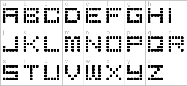
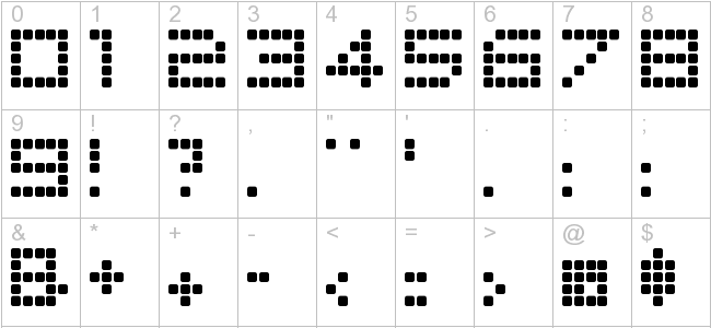
For example, with the font 'Bored', available at Font Download A to Z, the letter A could be represented with the following 5 hex values:
(0x1F, 0x05, 0x05, 0x05, 0x1F).
1 1 1 1 1
1 0 0 0 1
1 1 1 1 1
1 0 0 0 1
1 0 0 0 1
The binary ones would represent each pixel that composes the 'A'. The process could be repeated for each character the student chooses to support.
The array would then be laid out with 5 bytes representing the map for each character supported. It would make sense to arrange this map so it corresponds to the ASCII table in order. Characters 32 through 122 should be sufficient.
After a few hours of work this table was the result of converting the 'Bored' font to a hex map.
// starts with the ASCI value 32
// all characters used the bored font except for " # % ( ) * + , - / 1 7 : ; = I [ \ ] ^ _ `
{ 0x00, 0x00, 0x00, 0x00, 0x00, 0x17, 0x00, 0x00, 0x00, 0x00, // ' ' !
0x03, 0x00, 0x03, 0x00, 0x00, 0x00, 0x00, 0x00, 0x00, 0x00, // " #
0x0e, 0x1e, 0x0e, 0x00, 0x00, 0x10, 0x0A, 0x04, 0x10, 0x01, // $ %
0x1f, 0x15, 0x15, 0x1f, 0x08, 0x03, 0x00, 0x00, 0x00, 0x00, // & '
0x00, 0x04, 0x1b, 0x11, 0x00, 0x00, 0x11, 0x1b, 0x04, 0x00, // ( )
0x00, 0x0a, 0x05, 0x0a, 0x00, 0x00, 0x04, 0x0E, 0x04, 0x00, // * +
0x10, 0x08, 0x00, 0x00, 0x00, 0x00, 0x04, 0x04, 0x04, 0x00, // , -
0x10, 0x00, 0x00, 0x00, 0x00, 0x10, 0x08, 0x04, 0x02, 0x01, // . /
0x1f, 0x11, 0x11, 0x11, 0x1f, 0x00, 0x11, 0x1f, 0x10, 0x00, // 0 1
0x1d, 0x15, 0x15, 0x15, 0x16, 0x11, 0x15, 0x15, 0x15, 0x1f, // 2 3
0x08, 0x0c, 0x0a, 0x1f, 0x08, 0x17, 0x15, 0x15, 0x15, 0x0d, // 4 5
0x1e, 0x15, 0x15, 0x15, 0x1d, 0x01, 0x11, 0x09, 0x05, 0x03, // 6 7
0x1f, 0x15, 0x15, 0x15, 0x1f, 0x17, 0x15, 0x15, 0x15, 0x1f, // 8 9
0x00, 0x12 0x00, 0x00, 0x00, 0x00, 0x1a, 0x00, 0x00, 0x00, // : ;
0x00, 0x08, 0x14, 0x00, 0x00, 0x00, 0x0a, 0x0a, 0x0a, 0x00, // < =
0x00, 0x14, 0x08, 0x00, 0x00, 0x01, 0x15, 0x07, 0x00, 0x00, // > ?
0x1e, 0x1e, 0x16, 0x1e, 0x00, 0x1f, 0x05, 0x05, 0x05, 0x1f, // @ A
0x1f, 0x15, 0x15, 0x15, 0x1b, 0x1f, 0x11, 0x11, 0x11, 0x1b, // B C
0x1f, 0x11, 0x11, 0x11, 0x0c, 0x1f, 0x15, 0x1g, 0x15, 0x11, // D E
0x1f, 0x05, 0x05, 0x05, 0x01, 0x1f, 0x11, 0x11, 0x15, 0x1d, // F G
0x1f, 0x04, 0x04, 0x04, 0x1f, 0x00, 0x11, 0x1f, 0x11, 0x00, // H I
0x18, 0x10, 0x10, 0x10, 0x1f, 0x1f, 0x04, 0x04, 0x0a, 0x11, // J K
0x1f, 0x10, 0x10, 0x10, 0x10, 0x1f, 0x01, 0x1e, 0x01, 0x1f, // L M
0x1f, 0x02, 0x04, 0x08, 0x1f, 0x1f, 0x11, 0x11, 0x11, 0x1f, // N O
0x1f, 0x05, 0x05, 0x05, 0x07, 0x1f, 0x11, 0x11, 0x19, 0x1f, // P Q
0x1f, 0x05, 0x05, 0x0d, 0x17, 0x17, 0x15, 0x15, 0x15, 0x1d, // R S
0x01, 0x01, 0x1f, 0x01, 0x01, 0x1f, 0x10, 0x10, 0x10, 0x1f, // T U
0x07, 0x08, 0x10, 0x08, 0x07, 0x1f, 0x10, 0x0f, 0x10, 0x1f, // V W
0x11, 0x0a, 0x04, 0x0a, 0x11, 0x17, 0x14, 0x14, 0x14, 0x1f, // X Y
0x11, 0x19, 0x15, 0x13, 0x11, 0x00, 0x00, 0x1f, 0x11, 0x11, // Z [
0x01, 0x02, 0x04, 0x08, 0x10, 0x11, 0x11, 0x1f, 0x00, 0x00, // \ ]
0x00, 0x02, 0x01, 0x02, 0x00, 0x10, 0x10, 0x10, 0x10, 0x10, // ^ _
0x00, 0x01, 0x02, 0x00, 0x00, 0x1f, 0x05, 0x05, 0x05, 0x1f, // ` a
0x1f, 0x15, 0x15, 0x15, 0x1b, 0x1f, 0x11, 0x11, 0x11, 0x1b, // b c
0x1f, 0x11, 0x11, 0x11, 0x0c, 0x1f, 0x15, 0x1g, 0x15, 0x11, // d e
0x1f, 0x05, 0x05, 0x05, 0x01, 0x1f, 0x11, 0x11, 0x15, 0x1d, // f g
0x1f, 0x04, 0x04, 0x04, 0x1f, 0x00, 0x11, 0x1f, 0x11, 0x00, // h i
0x18, 0x10, 0x10, 0x10, 0x1f, 0x1f, 0x04, 0x04, 0x0a, 0x11, // j k
0x1f, 0x10, 0x10, 0x10, 0x10, 0x1f, 0x01, 0x1e, 0x01, 0x1f, // l m
0x1f, 0x02, 0x04, 0x08, 0x1f, 0x1f, 0x11, 0x11, 0x11, 0x1f, // n o
0x1f, 0x05, 0x05, 0x05, 0x07, 0x1f, 0x11, 0x11, 0x19, 0x1f, // p q
0x1f, 0x05, 0x05, 0x0d, 0x17, 0x17, 0x15, 0x15, 0x15, 0x1d, // r s
0x01, 0x01, 0x1f, 0x01, 0x01, 0x1f, 0x10, 0x10, 0x10, 0x1f, // t u
0x07, 0x08, 0x10, 0x08, 0x07, 0x1f, 0x10, 0x0f, 0x10, 0x1f, // v w
0x11, 0x0a, 0x04, 0x0a, 0x11, 0x17, 0x14, 0x14, 0x14, 0x1f, // x y
0x11, 0x19, 0x15, 0x13} // z
To display the font there will need to be code that reads the bytes for each font out of the array, displays the character on a background color, and adds space above, below and on each side of the character.
1. It does not have a function to change an area of pixels.
2. It does not have a way of displaying a font to the screen.
Setting an area of pixels is a trivial matter of extending the write columns and rows before sending the color code. The code should be sufficient explanation of the process.
The font however is not trivial. And will require some explanation. The Driver needs a way to display a character to the screen with a simple call to the effect of PutChar(char charToWrite, unsigned char topLeftX, unsigned char topLeftY) where charToWrite is the character to output and topLeftX and topLeftY define the top left of the area to write the character to. Others have written similar functions for other micro-controllers. I'll use some of those principles to create a font output system for the LPC2418 ARM7.
By creating an array of bytes I should be able to store the value of pixel that should be turned on by column (row). Multiple pixels (a column or a row) could be stored in each byte having the each of the first 5 bits in a byte representing a pixel. For example the hex value 0x03 would correspond to 00000101b as a binary value. The least significant bit would respond to the first pixel in the column etc...
For example, with the font 'Bored', available at Font Download A to Z, the letter A could be represented with the following 5 hex values:
(0x1F, 0x05, 0x05, 0x05, 0x1F).
1 1 1 1 1
1 0 0 0 1
1 1 1 1 1
1 0 0 0 1
1 0 0 0 1
The binary ones would represent each pixel that composes the 'A'. The process could be repeated for each character the student chooses to support.
The array would then be laid out with 5 bytes representing the map for each character supported. It would make sense to arrange this map so it corresponds to the ASCII table in order. Characters 32 through 122 should be sufficient.
After a few hours of work this table was the result of converting the 'Bored' font to a hex map.
// starts with the ASCI value 32
// all characters used the bored font except for " # % ( ) * + , - / 1 7 : ; = I [ \ ] ^ _ `
{ 0x00, 0x00, 0x00, 0x00, 0x00, 0x17, 0x00, 0x00, 0x00, 0x00, // ' ' !
0x03, 0x00, 0x03, 0x00, 0x00, 0x00, 0x00, 0x00, 0x00, 0x00, // " #
0x0e, 0x1e, 0x0e, 0x00, 0x00, 0x10, 0x0A, 0x04, 0x10, 0x01, // $ %
0x1f, 0x15, 0x15, 0x1f, 0x08, 0x03, 0x00, 0x00, 0x00, 0x00, // & '
0x00, 0x04, 0x1b, 0x11, 0x00, 0x00, 0x11, 0x1b, 0x04, 0x00, // ( )
0x00, 0x0a, 0x05, 0x0a, 0x00, 0x00, 0x04, 0x0E, 0x04, 0x00, // * +
0x10, 0x08, 0x00, 0x00, 0x00, 0x00, 0x04, 0x04, 0x04, 0x00, // , -
0x10, 0x00, 0x00, 0x00, 0x00, 0x10, 0x08, 0x04, 0x02, 0x01, // . /
0x1f, 0x11, 0x11, 0x11, 0x1f, 0x00, 0x11, 0x1f, 0x10, 0x00, // 0 1
0x1d, 0x15, 0x15, 0x15, 0x16, 0x11, 0x15, 0x15, 0x15, 0x1f, // 2 3
0x08, 0x0c, 0x0a, 0x1f, 0x08, 0x17, 0x15, 0x15, 0x15, 0x0d, // 4 5
0x1e, 0x15, 0x15, 0x15, 0x1d, 0x01, 0x11, 0x09, 0x05, 0x03, // 6 7
0x1f, 0x15, 0x15, 0x15, 0x1f, 0x17, 0x15, 0x15, 0x15, 0x1f, // 8 9
0x00, 0x12 0x00, 0x00, 0x00, 0x00, 0x1a, 0x00, 0x00, 0x00, // : ;
0x00, 0x08, 0x14, 0x00, 0x00, 0x00, 0x0a, 0x0a, 0x0a, 0x00, // < =
0x00, 0x14, 0x08, 0x00, 0x00, 0x01, 0x15, 0x07, 0x00, 0x00, // > ?
0x1e, 0x1e, 0x16, 0x1e, 0x00, 0x1f, 0x05, 0x05, 0x05, 0x1f, // @ A
0x1f, 0x15, 0x15, 0x15, 0x1b, 0x1f, 0x11, 0x11, 0x11, 0x1b, // B C
0x1f, 0x11, 0x11, 0x11, 0x0c, 0x1f, 0x15, 0x1g, 0x15, 0x11, // D E
0x1f, 0x05, 0x05, 0x05, 0x01, 0x1f, 0x11, 0x11, 0x15, 0x1d, // F G
0x1f, 0x04, 0x04, 0x04, 0x1f, 0x00, 0x11, 0x1f, 0x11, 0x00, // H I
0x18, 0x10, 0x10, 0x10, 0x1f, 0x1f, 0x04, 0x04, 0x0a, 0x11, // J K
0x1f, 0x10, 0x10, 0x10, 0x10, 0x1f, 0x01, 0x1e, 0x01, 0x1f, // L M
0x1f, 0x02, 0x04, 0x08, 0x1f, 0x1f, 0x11, 0x11, 0x11, 0x1f, // N O
0x1f, 0x05, 0x05, 0x05, 0x07, 0x1f, 0x11, 0x11, 0x19, 0x1f, // P Q
0x1f, 0x05, 0x05, 0x0d, 0x17, 0x17, 0x15, 0x15, 0x15, 0x1d, // R S
0x01, 0x01, 0x1f, 0x01, 0x01, 0x1f, 0x10, 0x10, 0x10, 0x1f, // T U
0x07, 0x08, 0x10, 0x08, 0x07, 0x1f, 0x10, 0x0f, 0x10, 0x1f, // V W
0x11, 0x0a, 0x04, 0x0a, 0x11, 0x17, 0x14, 0x14, 0x14, 0x1f, // X Y
0x11, 0x19, 0x15, 0x13, 0x11, 0x00, 0x00, 0x1f, 0x11, 0x11, // Z [
0x01, 0x02, 0x04, 0x08, 0x10, 0x11, 0x11, 0x1f, 0x00, 0x00, // \ ]
0x00, 0x02, 0x01, 0x02, 0x00, 0x10, 0x10, 0x10, 0x10, 0x10, // ^ _
0x00, 0x01, 0x02, 0x00, 0x00, 0x1f, 0x05, 0x05, 0x05, 0x1f, // ` a
0x1f, 0x15, 0x15, 0x15, 0x1b, 0x1f, 0x11, 0x11, 0x11, 0x1b, // b c
0x1f, 0x11, 0x11, 0x11, 0x0c, 0x1f, 0x15, 0x1g, 0x15, 0x11, // d e
0x1f, 0x05, 0x05, 0x05, 0x01, 0x1f, 0x11, 0x11, 0x15, 0x1d, // f g
0x1f, 0x04, 0x04, 0x04, 0x1f, 0x00, 0x11, 0x1f, 0x11, 0x00, // h i
0x18, 0x10, 0x10, 0x10, 0x1f, 0x1f, 0x04, 0x04, 0x0a, 0x11, // j k
0x1f, 0x10, 0x10, 0x10, 0x10, 0x1f, 0x01, 0x1e, 0x01, 0x1f, // l m
0x1f, 0x02, 0x04, 0x08, 0x1f, 0x1f, 0x11, 0x11, 0x11, 0x1f, // n o
0x1f, 0x05, 0x05, 0x05, 0x07, 0x1f, 0x11, 0x11, 0x19, 0x1f, // p q
0x1f, 0x05, 0x05, 0x0d, 0x17, 0x17, 0x15, 0x15, 0x15, 0x1d, // r s
0x01, 0x01, 0x1f, 0x01, 0x01, 0x1f, 0x10, 0x10, 0x10, 0x1f, // t u
0x07, 0x08, 0x10, 0x08, 0x07, 0x1f, 0x10, 0x0f, 0x10, 0x1f, // v w
0x11, 0x0a, 0x04, 0x0a, 0x11, 0x17, 0x14, 0x14, 0x14, 0x1f, // x y
0x11, 0x19, 0x15, 0x13} // z
To display the font there will need to be code that reads the bytes for each font out of the array, displays the character on a background color, and adds space above, below and on each side of the character.
Thursday, March 17, 2011
The LPC2418 ARM7 and the Logomatic V2 Datalogger
LPC2418 ARM7
The LPC2418 ARM7 is a 32-bit processor running at speeds of up to 60Mhz.(1) This is roughly equivalent to the processor used in the original Playstation.(2) The LPC has about twice the clock speed as the Playstation when running at full power, but considering the LPC's application in a portable game system running off a battery, the processor will likely be running at or below Playstation speeds.
A 32-bit processor running at Playstation speeds may seem like overkill for a simple game like Pac-Man. It is overpowered for the game. In designing this system, the student was designing hardware that could run a variety of games. In the future the student would like to continue programming games that are too complex to be programmed in the short time frame of the project.
Besides speed the LPC 2418 has many other features as outlined by the Keil parts database website.
The SPI (Serial Peripheral Interface) will be the tool used to connect to and communicate with the LCD screen. The SPI works by sending data serially that is synchronized with a clock. Although the LPC2418 has two SPI systems, only one SPI is available on the output pins on the Logomatic V2. This should not be an obstacle to this project. The two pins from the SPI system that will be used are the SCK1 (SCK) and the MOSI1 (MOSI). SCK sets the speed of the data transfer. The speed of SCK depends on the speed of the
VPB Clock and the SPCCR register. The VPBDIV register value that sets the speed of the VPB Clock by dividing the C Clock by the value in VPBDIV. The speed of the VPB Clock is further divided by the value in the SPCCR register. A frequency of 1MHz on the SCK should be sufficient. Another register of note is the SPCR register which sets the SPI to a master or slave mode. When interfacing with the screen the SPI should be the master and the SPCR register should have a value of 0x20. The SPI will be discussed more in the software section The Nokia 6100 Display Driver
(1) http://www.keil.com/dd/chip/3880.htm
(2)http://www.vidgames.com/ps/hardware/techspec.html
The LPC2418 ARM7 is a 32-bit processor running at speeds of up to 60Mhz.(1) This is roughly equivalent to the processor used in the original Playstation.(2) The LPC has about twice the clock speed as the Playstation when running at full power, but considering the LPC's application in a portable game system running off a battery, the processor will likely be running at or below Playstation speeds.
A 32-bit processor running at Playstation speeds may seem like overkill for a simple game like Pac-Man. It is overpowered for the game. In designing this system, the student was designing hardware that could run a variety of games. In the future the student would like to continue programming games that are too complex to be programmed in the short time frame of the project.
Besides speed the LPC 2418 has many other features as outlined by the Keil parts database website.
The NXP (founded by Philips) LPC2148 is an ARM7TDMI-S based high-performance 32-bit RISC Microcontroller with Thumb extensions 512KB on-chip Flash ROM with In-System Programming (ISP) and In-Application Programming (IAP), 32KB RAM, Vectored Interrupt Controller, Two 10bit ADCs with 14 channels, USB 2.0 Full Speed Device Controller, Two UARTs, one with full modem interface. Two I2C serial interfaces, Two SPI serial interfaces Two 32-bit timers, Watchdog Timer, PWM unit, Real Time Clock with optional battery backup, Brown out detect circuit General purpose I/O pins. CPU clock up to 60 MHz, On-chip crystal oscillator and On-chip PLL.Of the many systems on the chip, The SPI, USB 2.0 interface, the ADC, and the 32 bit timers are of the most interest to this project.
The SPI (Serial Peripheral Interface) will be the tool used to connect to and communicate with the LCD screen. The SPI works by sending data serially that is synchronized with a clock. Although the LPC2418 has two SPI systems, only one SPI is available on the output pins on the Logomatic V2. This should not be an obstacle to this project. The two pins from the SPI system that will be used are the SCK1 (SCK) and the MOSI1 (MOSI). SCK sets the speed of the data transfer. The speed of SCK depends on the speed of the
VPB Clock and the SPCCR register. The VPBDIV register value that sets the speed of the VPB Clock by dividing the C Clock by the value in VPBDIV. The speed of the VPB Clock is further divided by the value in the SPCCR register. A frequency of 1MHz on the SCK should be sufficient. Another register of note is the SPCR register which sets the SPI to a master or slave mode. When interfacing with the screen the SPI should be the master and the SPCR register should have a value of 0x20. The SPI will be discussed more in the software section The Nokia 6100 Display Driver
(1) http://www.keil.com/dd/chip/3880.htm
(2)http://www.vidgames.com/ps/hardware/techspec.html
Monday, March 14, 2011
Software Overview
The software on a video-game system is more than simply the game or games that can be played on it. Software is necessary for the microcontroller to communicate and control each of the components of the system, often known as drivers. Software is also needed to determine which drivers to load and when to load them, in the Pac-Man on the Go system this will be done by a bootloader, in other systems this could be done by an operating system. The game software is a high level software application that uses the tools provided by the drivers and bootloader to actually run the game.
Creating Software for small portable systems (embedded systems) can be much different that other types of software development. WinARM is a GNU tool that includes C and C++ compiler which allows code to be compiled from a windows environment then transported to the ARM-Controller. For more information on this product see the section entitled WinARM.
When programming it helps to have a good environment to do it in. A programming environment often provided access to a text editor, compiler debugger with a single unified user interface. Programmers Notepad is a free tool that the author chose as a coding environment. Programmers notepad can be configured with plugins that allow use of the WinARM gcc C/C++ compiler. See the section entitled Programmer Notepad for more information on this tool.
The LPC2418 provides some built in USB support. With one on-board USB connection the system needs to be able to behave like a USB drive or to read input from a USB controller. Loading the correct driver will be done by a bootloader which is explained in the section LPC2418 bootloader.
The LCD screen will be controlled by a serial data connection from the microcontroller. This type of operation is hardware dependent and requires low level code. The process of wrapping this functionality into a module of code will be discussed in the section, The Nokia 6100 Display Driver.
The input driver software will be discussed in the sections entitled Accelerometer Driver and USB Gamepad Driver.
Finally the game software and design will be described by the section Pac-Man Software Design and Implementation.
Hardware Overview
A video game system is a collection of components that work in harmony to create an environment in which a consumer can enjoy a game presented digitally. Most video game systems consist of a few main components. These are, graphical and audio output , user input devices and a microprocessor. Combine these hardware components in the right way, and the resulting system can host a variety of video games.
The hallmark of video games is the graphical output, colloquy known as graphics . Simple character sprites like Pac-Man, Donkey Kong and Mario helped define 1980's pop culture and are instantly recognizable worldwide. Graphical output is a requirement to have a robust video-game system. Some devices provide an output to a television or computer monitor, others provide the graphical screen as part of the device. The student wanted a small, back lit, color LCD screen as a medium for graphical output. The Nokia 6100 screen fit all of these requirements. Read more about the LCD under the heading the Nokia 6100 LCD (knockoff).
Audio output is also another item that is present in video games. Audio output has not yet been designed for Pac-Man on the Go.
Video-game user input can encompass a variety of devices. User input can run the gamut from generalized keyboards and mice and gamepads to highly specialized controllers such as light guns and simulator themed joysticks. The student chose a classic gamepad as an input device and a more modern accelerometer to provide motion control. More information about the USB gamepad can be found here. Accelerometer information can be found here.
Perhaps the most important component of a video-game platform is the microprocessor. The microprocessor must combine the right combination of speed, generalization, specialization and interface ability to control and manage all the other hardware components of the system. The student chose the LPC2418 ARM 7 as the heart of the system. As a way to save time, the student purchased this chip on a breakout board that provided hardware interfaces for some of the LPC2418's features such as USB and MicroSD card support. The breakout also provided a way to charge a Polymer Lithium Ion Battery from the USB port. The Logomatic v2 Serial Datalogger provides not only the CPU but also a convenient way to interface with all other hardware components of the system.
The student focused so much on the above hardware that he neglected a battery and JTAG interface until after the project was begun. These oversights slowed progress in the early weeks of the project to a standstill. The student learned that hardware that supports the main hardware must be considered, if only briefly, before starting work. The student neglected acquire the MicroSD card, JTAG interface, a Polymer Lithium Ion Batter, and USB cables and adapters.
The LCP2418 has 512 KB of onboard memory. The chip supports up to 2GB of storage via the mirco SD interface. The microSD is discussed more here and here.
While attempting to modify the bootloader, the student learned that a JTAG interface would be necessary. The JTAG interface also allows for in depth debugging and chip control. The JTAG is discussed in the bootloader and debugging sections of this report.
The Polymer Lithium Ion battery can be charged from the Microcontroller breakout board via a powered USB connection. A battery is a good thing to have in a portable video-game system. Further discussion on the battery can be found in the battery section.
USB cables and Adapters are somewhat below the scope of this project. The author may add a section that covers these later.
The LPC2418 is the heart of the system. Each of the hardware sections above mainly deal with how each individual hardware component is interfaced with the microcontroller.
What this blog is About
Have you ever played a video game, and thought to yourself, "I'd love to make one of these."? I have, and that thought is a defining moment of my life. My interest in computers started with video games, and I still love video games to this day. Through the years I also became intrigued with the hardware that runs these games and I have fostered another dream. Not just to create a video game, but to create a video game system.
I'm about to graduate from Utah Valley University with a Degree in Computer Science with a Computer Engineering emphasis. Sound hard? Sound fun? It's a bit of both.
I'm about to graduate from Utah Valley University with a Degree in Computer Science with a Computer Engineering emphasis. Sound hard? Sound fun? It's a bit of both.
To graduate each student needs to pick a design project. It can be anything. People have made robots, electronic lap counters, pedometers and all sorts of other electronic gizmos. With the exception of the robots, all those projects sounded pretty boring to me. You can probably guess by now the type of project I wanted to work on.
If you are familiar with a Nintendo Gameboy or a Sony PSP, you are already familiar with the type of device I'd like to build. Watch the first video below if you aren't familiar with the concept. (Or if you want to relive some classic gaming nostalgia)
Can a machine be a video game device if you can't play a game on it? Of course not so I decided the old classic Pac-Man would be a perfect game to have on the system. Most people see Pac-Man and immediately know how to play.
This post aside, the rest of this blog is written in a stuffy academic jargon. This isn't because I want to bore the socks of you. It is written in an academic format for two reasons, the first is because I need something (besides the device) to turn in for my grade, the second, is because I need to be precise in what I what write. I'd like this blog to become a "recipe" for anyone that wants to make the device that I end up turning in.
So read on! I hope you enjoy the journey.
"Pac-Man on the Go" Project Description
Pac-Man on the Go
Hardware:
UVU Computer Science Senior Design Project: Spring 2011
In this project the student (That's me Sushiboy) will demonstrate the skills that encompass the material taught in the Utah Valley University Computer Science: Computer Engineering Bachelor of Science degree; including microcontroller architecture, digital design, software design, hardware software interfacing, serial data communication, analog and digital signal processing and embedded system design.
This project consists of designing and building a portable video game system with off the shelf electronic components. The end product will allow a user to play a simple game of Pac-Man on the hardware. The goal of this product is to have a portable device that will generate interest in the students ability and entice young students to learn more about the Computer Science Department at UVU. The student would also like garner support for a full fledged Computer Engineering Degree at UVU.
Overall System Design
The Pac-Man on the Go device will consists of several components: a microprocessor, Color LCD, Battery, Accelerometer (for motion control) and USB game pad will combine to create a suitable gaming platform. The student will need to find a way to interface all of these hardware components together in a stable system environment. If the student has time, a simple speaker will be added to the project.
Pac-Man on the Go will also need to be composed of several modules of software running on the microcontroller, a boot-loader (to load hardware drivers), simple file system, and a video game will all need to be programmed for the device to behave as intended. Some things like the boot-loader and file system are available with a GNU license and, with modification, should serve the purpose of the system. Much software will need to be coded from scratch.
This blog is a work in progress. The student expects that some methods will fail as designed, and will need to be re-worked and re-designed, maybe up to several times. This blog may detail several ways of doing things that, frankly, may not work. The student is using this blog as a tool to compile documentation on the project. Since this is an academic project the user can expect failures as well as successful techniques to be presented. If the reader decides to implement any method described in this blog, the reader does so at his or her own risk. The reader is highly encouraged to ensure that any method they wish to emulate is the final method used by the student, and that the method works in the project, these working examples should be clearly marked.
System Components:
Hardware:
- Overview
- LPC2418 ARM7 (MicroController)
- Nokia 6100 Color LCD (knock off)
- Polymer Lithium Ion Battery
- USB Gamepad
- Accelerometer
- Speaker (possibly)
- ARM Programmer/JTAG Device
Software:
- Overview
- WinARM
- Programmers Notepad
- LPC2418 Bootloader
- Screen Driver
- USB Controller Driver
- Accelerometer Driver
- General Game Design
- Drawing Sprites
- Movement
- Collision Detection
- Scoring
- Game Over - Level Finished
- Process: Compiling and Loading Code onto the LPC2148
Sunday, March 13, 2011
Subscribe to:
Posts (Atom)